https://github.com/walter426/Matlab_DSMA_Utilities/tree/master/DSMA_Utilities/M_Ary_QSMDR_Generator
As mentioned in the title, it is a Digital Signal Processing stuff, but it can be applied to other fields which need to determine any 2D decision regions... (It sounds shit to laymen...)
Below is a brief lesson for background started from the point of view under signal processing.
Fig 1: Constellation Diagram
During a physical communication, a set of signals called
Modulation Scheme is used to indicate information(e.g. '00', '11', '10...) to be transmitted. The signal in a
Modulation Scheme can be represented by a set of
orthogonal signals called
Signal Space. The number of the
orthogonal signals is thus the number of dimensions of the
signal space. Then, a
Modulation Scheme can be
represented as a set of point
symbol in the
Signal Space that is called a
Constellation Diagram.
Fig.2: Decision Region
During a transmission, it is normal that the signal will suffer noise from the environment, that represents as a displacement of symbol in the
Signal Space. If Noise is high enough, the transmitted symbol may be shifted to a location close to other symbol so that the receiver will de-modulate out wrong symbol. So it is important to keep sufficient distance between each signal symbol pairs in the
Modulation Scheme in the
signal space if noise is quite high. The distance implies each symbol has its own optimal
decision region in the
signal space to minimize the
Symbol Error Ratio and thus the
Bit Error Rate.

Now make a break of the lesson, let me recall the aim of the
M-Ary Quadrature Signal Modulation Decision Region Generator(
M-Ary QSMDR Generator). The aim of the
M-Ary QSMDR Generator is to "
Draw Optimal Decision Regions of any number of Signal Symbol in a 2-Dimensional Signal Space".
Below is the brief description of the main project files,
M_Ary_QSMDR_Generator.m: Create Arguments(e.g. Signal Set, Probability Set) for
SignalSymbolDecisionRegionGenerator.m
SignalSymbolDecisionRegionGenerator.m: Create and Draw the Decision Regions of the input Signal Symbol.
SignalSymbolDecisionBdry.m: Create Decision Boundary between two signal symbols with given probabilities of the symbols and the Additive White Gaussian Noise(
AWGN) .
Based on previous background and description, it's time to explain the algorithm which is implemented in
SignalSymbolDecisionRegionGenerator.m.
A. Create Boundary Line between Signal Symbol pair:
- Every Signal Symbol pair are put into
SignalSymbolDecisionBdry.m to create its Decision Boundary based on below criteria.
Fig 3. Decision Boundary Criteria
Fig 4: Decision Regions before truncation
After all boundary line are drawn, it is obvious that every signal symbol need the boundary segments closest to it only. The other boundary segments can be truncated on the diagram.
At this step,
the optimal decision region problem becomes a Geometry problem.
B. Cut unnecessary boundary segment
To be honest, it is not easy to archive this task. Fortunately, I found out this is possible if treat the lines in the constellation diagram as vectors. By comparing the angles between those vectors, it is possible to get which boundary segments are closest to the symbol. Below is the
Vector Angle Comparison Criteria.
By above Four criteria, the unnecessary boundary segments is able to be determined, and then truncated on the
Decision Region diagram.
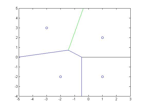
Below are some examples of the Decision Region generated,
Comment:
This stuff is the most difficult project I have ever made before...
The difficulty is on the discovery on the relations between symbols and their intercepted boundary lines...